How To Install A GFCI Outlet: A DIY Guide
We may receive a commission on purchases made from links.
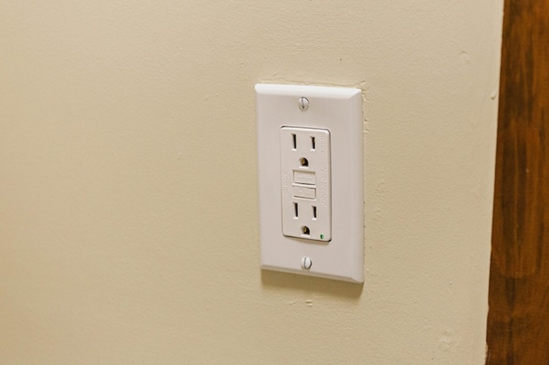
A GFCI outlet, officially known as a ground-fault circuit-interrupter receptacle, helps to prevent electrical shock in wet areas, like kitchens, bathrooms and the outdoors. GFCI protection is required by the National Electrical Code in these areas of the home as well as in laundry rooms, garages, basements and crawl spaces. Replacing an existing standard electrical outlet with a GFCI receptacle is an easy way to improve safety and can be an efficient option for bringing a new installation up to current code standards if you're remodeling or just updating some wiring. Always check with the local code authority for requirements specific to your project.
Wiring a GFCI outlet is no more difficult than connecting a standard outlet, but you need to choose one of two different wiring configurations for the GFCI. Use the single-location configuration if you want to protect only the new GFCI outlet, and use the multiple-location configuration if you want to protect the GFCI outlet and the rest of the outlets and other devices on the "downstream," or load side, of the circuit. The load side is fed by the power coming out of the GFCI receptacle as opposed to the line side, which lies between the circuit breaker (in the home's service panel, or breaker box) and the GFCI receptacle. (See below for more details on single-location and multiple-location wiring.)
Warning
Make sure the new GFCI outlet and any wiring you install has the same amperage and voltage ratings as the original outlet and circuit wiring. Most 120-volt outlets are 15-amp (using 14-gauge wire) or 20-amp (using 12-gauge wire).
Things Needed
-
NM-B cable or THHN wire (as needed)
-
Wire connectors (as needed)
-
Outlet tester (optional)
How to Install a GFCI Outlet
1. Turn Off the Power
Turn the power off to the circuit supplying the outlet you will replace by switching off the circuit breaker in your home's service panel (breaker box).
2. Test for Power
Confirm the power is off at the outlet using a noncontact voltage tester. Insert the tip of the tester into each of the outlet slots; it should detect no voltage in any slot. If the tester signals that there is voltage, return to the service panel, shut off the correct breaker and then test the outlet again to make sure the power is off.
 Carrie Waller for Hunker
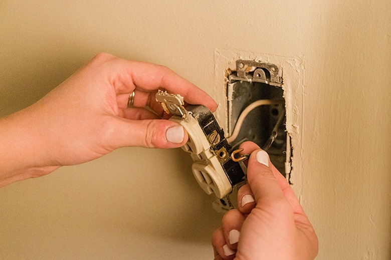
3. Pull Out the Old Outlet
Remove the outlet cover plate's screw using a screwdriver and pull off the cover plate. Remove the two outlet mounting screws securing the outlet to the electrical box. Grasp the mounting ears at the top and bottom of the outlet and carefully pull the outlet a few inches away from the box without touching any wires. Test each wire in the box with the voltage tester to double-check that the power is off. (It's unlikely but possible that additional wires in the box are part of a different circuit that is not shut off).
4. Remove the Old Outlet
Unscrew each screw terminal containing a wire and pull the wire from the terminal. If the wires are inserted into the back of the outlet (called back-wiring), insert a small flathead screwdriver into the slot above each wire hole to release the wire or you can simply cut off the wires as close as possible to the outlet using wire strippers or cutting pliers.
5. Examine the Wires
Separate and straighten all of the wires to examine them. If there is only one cable (one set of wires) in the box, this indicates that the outlet is at the end of the circuit. In this case, you must install the GFCI using the single-location configuration. If there are two cables (two sets of wires) and you wish to use single-location wiring for the GFCI, you must pair the wires by color and add a pigtail wire to each pair (see How to Make Pigtail Wires below). If there are two cables and you want to wire the GFCI for multiple-location protection, you must determine which of the cables is the line cable, through which the power comes in from the service panel (see Identifying the Line Cable below).
6. Prepare the Wires
Inspect the bare-metal end of each wire. It should be clean and undamaged and extend about 3/4 inch beyond the wire insulation. If the bare end has nicks, burn marks or other damage, trim off the bare end using wire strippers and then strip 3/4 inch of insulation from the cut end. Use the wire strippers or needle-nose pliers to shape the bare end into a hook.
7. Connect the Wires to the GFCI
Connect the hot (usually black), neutral (usually white) and ground (usually bare copper or green insulated) wires to the new GFCI outlet based on the desired configuration. Join each wire to the outlet by hooking the wire (or pigtail) onto the appropriate screw terminal so that the open side of the wire hook is on the right (this ensures that the hook closes as you tighten the terminal screw). Tighten each terminal screw firmly with a Phillips screwdriver.
- For single-location configuration: Connect the neutral wire to the terminal marked
"white line" or "neutral line" (or similar). Connect the hot wire to the
terminal marked "hot line." Connect the ground wire to the ground terminal. - For multiple-location configuration: Connect the neutral wire from the line cable
to the terminal marked "white line" or "neutral line" (or similar). Connect the
hot wire from the line cable to the terminal marked "hot line." Connect the
neutral wire from the other cable (the load cable) to the terminal marked
"white load" or "neutral load" (or similar) and connect the hot wire to the
"hot load" terminal. Connect the ground wire to the ground terminal.
Tip
Don't worry if there is no ground wire in the circuit cable(s). A GFCI still provides full electric shock protection without a ground connection (see What If There's No Ground Wire? below).
8. Secure the GFCI Outlet
Fold the wires and tuck them into the electrical box as you push the outlet into place. Secure the outlet to the box with its mounting screws. Install the new GFCI cover plate.
9. Restore Power and Test the Outlet
Restore power to the circuit by switching on the circuit breaker. Press the "reset" button on the face of the outlet to make the outlet live. Most GFCI outlets have red and green indicator lights; the green light will illuminate when the power is activated. Conduct a manual test of the GFCI device by pressing the "test" button on the outlet's face; you should hear a click, and the outlet will lose power. You will also see the green light go off and the red light go on. Press the "reset" button again to restore power, indicated by the green light as before.
Tip
You can test the outlet with a plug-in outlet tester to confirm that the outlet is wired correctly. An outlet tester simply plugs into the outlet and has three indicator lights. The light sequence will tell you if you've wired the outlet correctly or if you've missed something, like connecting the hot and neutral wires to the wrong terminals.
Single-Location vs. Multiple-Location Protection
Single-Location vs. Multiple-Location Protection
Choosing the wiring configuration for a new GFCI outlet is easier than it may seem. If you need just one GFCI outlet and there are no other outlets on the same circuit (for example, in a bathroom that has only one outlet), use the single-location wiring configuration. In rare cases, you may want to add GFCI protection at one outlet location and not at another outlet on the same circuit; this situation also calls for single-location protection.
Multiple-location protection is commonly used where two or more outlets on the same circuit require GFCI protection, such as in a kitchen, garage or basement or on multiple outdoor outlets on the same circuit. By installing a GFCI receptacle at the first outlet location using multiple-location wiring, you provide GFCI protection to all of the other outlets. The GFCI will protect itself and the other outlets, including standard (non-GFCI) outlets. Keep in mind that with this configuration, if the GFCI trips, it will shut off the power to all of the outlets, and you'll have to reset the GFCI to restore power. Also remember that the GFCI does not protect any outlets between itself and the service panel; the only way to do that is to install a GFCI circuit breaker.
How to Make Pigtail Wires
How to Make Pigtail Wires
A pigtail is a short length (about 6 inches) of wire that is joined to multiple circuit wires to create a single point of connection for all of the wires. When using the single-location configuration on a GFCI outlet, you must connect only one neutral, hot and ground wire to the outlet, and you cannot connect more than one wire to a single screw terminal with any type of outlet. Therefore, if there are two cables in the electrical box, you'll have two neutrals, two hots and two or more ground wires (there may be a third ground wire if the electrical box is metal, which must be grounded).
To create pigtails, you'll need about 6 inches of NM-B (nonmetallic) electrical cable that matches the cables in the box, or you can buy individual pieces of type-THHN insulated wire of the same gauge as the cable wire. Pull the wires out of the cable sheathing and strip about 3/4 inch of insulation from each end. Join one end to the matching wires in the circuit cables — neutral to neutral, hot to hot, ground to ground — using twist-on wire connectors (wire nuts) or push-in connectors (follow the connector manufacturer's instructions for how much to strip the wires). Shape the other end of the pigtail into a hook for connecting to the outlet's screw terminal.
Identifying the Line Cable
Identifying the Line Cable
When wiring a GFCI for multiple-location protection, the power must come into the "line" terminals and go out through the "load" terminals. Therefore, you need to identify which cable in the box is the line, or source, cable. If you don't know which cable is which, you can perform a simple test to identify the line cable. This is a live-wire test that can give you a painful shock if you're careless, so pay attention and be sure not to touch any wires with your hands during the test.
You conduct the test after the power has been shut off and you've removed the old outlet and separated all of the wires outside the box. Make sure none of the wires is touching one another or anything else. Restore power to the circuit by switching on the circuit breaker. (Make sure everyone in the house knows you are conducting the test so no one goes near the wires.) Touch the tip of a noncontact voltage tester to each of the two hot wires at the outlet box: The one that registers voltage is the line wire. Turn off the power again and then label the line hot wire and line neutral wire (the white wire in the same cable as the line hot wire) with masking tape; these are the wires you will connect to the "line" terminals on the GFCI outlet.
What If There’s No Ground Wire?
What If There's No Ground Wire?
If you live in an old house that has circuit cables with no ground wire, it's possible that there is a ground connection if the outlet box is metal and is connected to metal conduit, but such ground connections are often unreliable. If the box is not metal or there is no metal conduit, there is no ground connection present. In any case, the GFCI outlet will still provide ground-fault protection, but it does not provide a true ground. A true ground is needed for surge protectors and other electronic devices.
GFCI outlets are sold with little stickers that say "no equipment ground" or something similar. When installing a GFCI on an ungrounded circuit, place one of these stickers on the outlet cover plate. This will remind you that the circuit is ungrounded so it's not suitable for surge protectors or other equipment that requires a ground.