How To Wire An Outside AC Condenser
Making the electrical connections on a condenser is not a project a DIYer should normally attempt, as it involves high-voltage components and wiring connections that are difficult to access. These connections are usually made at the time an entire system is installed or replaced, and this is really the territory of a professional HVAC contractor or licensed electrician.
Replacing a condenser also involves cutting the lines that carry refrigerant, which can lead to spilling the liquid refrigerant, an environmental issue that your community will likely frown upon. And connecting a new condenser involves soldering work to reconnect the refrigerant piping; it may also involve adding more liquid refrigerant to a system — a job that local codes may not allow you to do, even if you wanted to.
For many reasons, then, this is not a DIY project for most people. However, if you are interested in learning more, read on.
About the Parts
About the Parts
The condenser is one of three crucial parts of a home air conditioning system. It is the component responsible for actually releasing the heat collected by the evaporator inside the home. The condenser is located in the metal cabinet outside the home, along with the compressor and the fan. The third critical component, the evaporator, is located inside the house near the furnace blower mechanism.
How Air Conditioning Works
How Air Conditioning Works
Although they can seem complicated, air conditioners work by fairly simple physics, taking advantage of the fact that liquids absorb heat as they change into a gas, while gases give off heat when they change back to liquids. It is the refrigerant inside sealed piping of the air conditioning system that performs this magic.
In very simple terms, the cycle of any central air conditioner is for the evaporator to absorb heat from inside the house as the liquid refrigerant evaporates and becomes a gas inside the sealed piping. The gaseous refrigerant then flows outside to the outdoor unit, where the compressor squeezes the gas back into liquid form. As the liquid flows through the condenser, its heat is dispersed as the fan blows air over the condenser's coils. The liquid refrigerant then is pumped back to the evaporator, where the cycle continues — gas to liquid, liquid to gas, transferring heat from one space to the other.
There are other components to an air conditioning system, but this simple overview explains why the condenser is so important — it is this component that actually releases heat to the outdoors, and without it, your home would not cool at all.
How an Air Conditioning Condenser Is Wired
How an Air Conditioning Condenser Is Wired
When a service professional has installed a new condenser and completed the refrigerant piping connections, hookup of the electrical wiring will go something like this:
The installer or electrician must install two sets of wires when connecting the condenser. Both are connected to the same contactor relay, located inside the condensing unit. One set of wires provides high-voltage 240-volt current that powers the fan and compressor unit, while the other set of wires are low-voltage wires that run from the thermostat and inside furnace unit to turn the outside condenser ON and OFF when needed.
References
Shutting Off the Power and Removing the Cover
The installer's first step will be to make sure the power is shut off. Normally this means he or she will shut off two circuit breakers — one labeled FURNACE or AIR HANDLER; the other labeled AC or AIR CONDITIONER.
Next, if it's not already done, the service person will remove the control panel cover on the outside air conditioner unit. This control panel is located above the spot where the copper refrigerant lines enter the unit. The control panel cover is pulled straight down to remove it from the condensing unit. Within the control panel, you will see a black block with screw terminal connections, as well as the can-shaped capacitor.
Connecting the Ground Wire and High-Voltage Wires
The high-voltage wires from the air conditioner disconnect box (usually mounted on an outside wall within arm's reach of the air conditioner unit) are now pushed up through the wire clamp in the bottom of the box. The high-voltage wires have two insulated power wires and one bare copper ground wire. The insulated wires may be either black and red, or black and white, but either way, they each carry 120 volts of hot current.
 Bryan Trandem
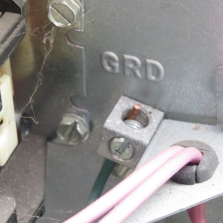
First, the bare copper ground wire is connected to the ground terminal block, using a flathead screwdriver. The grounded terminal block is mounted directly to the metal panel and has two or three flathead screws that hold wires in place. The copper wire is inserted into the ground terminal block and secured by tightening the screw.
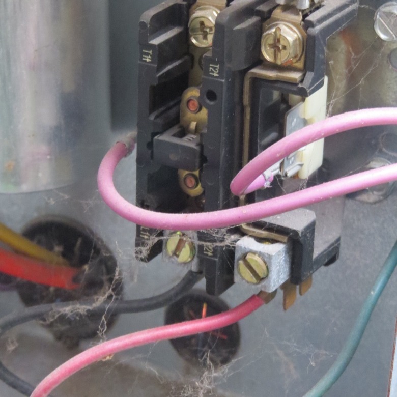
Now, the service person will strip about 1/2 inch of insulation from the ends of both insulated high-voltage wires, using wire strippers. The stripped end of these high-voltage wires are now inserted into the high-voltage wire terminals. In a 240-volt circuit, both the wires are hot, so it doesn't matter which screw terminal you connect them to. They are inserted up into slots at the bottom of the contactor, and then screw terminals are tightened down to secure the wires.
 Bryan Trandem
The contactor, a black box-shaped component with spring-loaded bus bars and a low-voltage operating coil, acts like a high-voltage switch. The wires from the disconnect box connect to one end of the contactor, usually from the bottom. The fan and compressor wires connect to the other end of the contactor, usually at the top, and are already attached by the manufacturer. The two hot wires from the disconnect box must be inserted fully into the contacts and the screws fully tightened.
Connecting the Low-Voltage Wires
The installer now pushes the low-voltage wire set into the control box through the access opening. The low-voltage wire set will have two individual wire strands inside of an outer plastic sheathing.
Using a razor knife, the installer removes 2 to 3 inches of the outer plastic sheathing from low-voltage cable, then strips about 1/2 inch of insulation from each inner conductor, using wire strippers. The low-voltage wires usually use white and red insulation, but the colors do not matter.
Now, the installer twists together either of the low-voltage wires from the contactor together with one of the low-voltage wires and secures them with a wire nut. He twists the remaining two wires together and secures them with a wire nut. Again, wire color combinations do not matter.
 Bryan Trandem
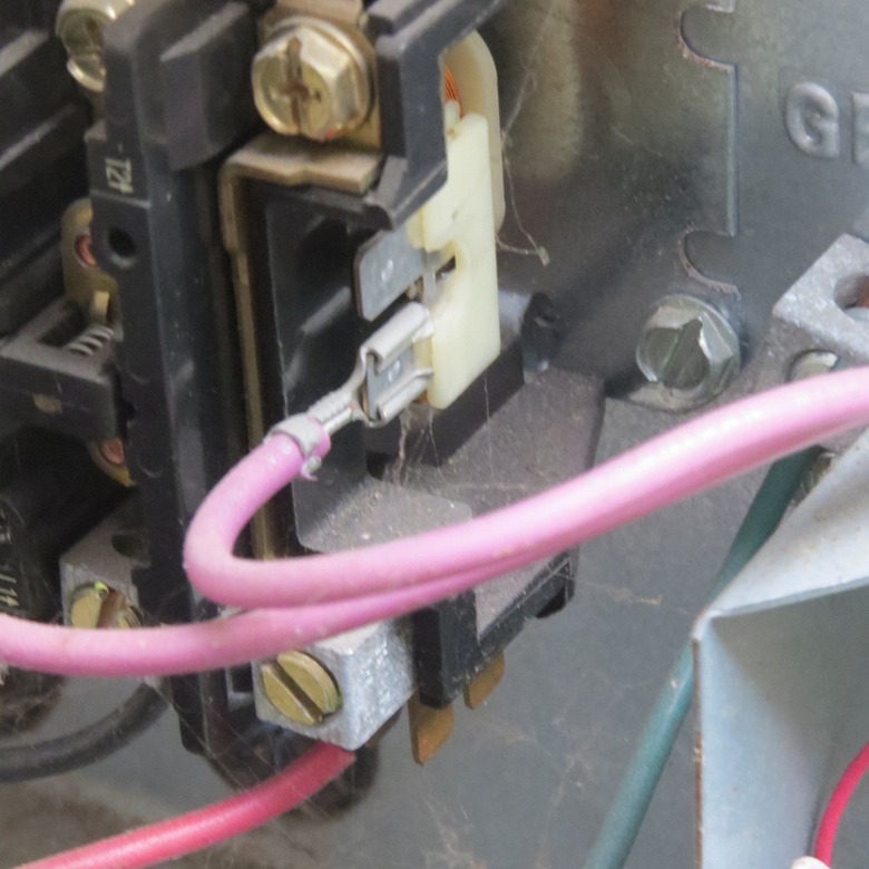
The ends of the low-voltage wires are attached to push fittings mounted on the side of the contactor block. Normally, these ends of the low-voltage wires will already be attached.
Completing the Installation
Finally, the installer will tighten the wire clamp with a flathead screwdriver, then replace the condensing unit's access cover and tighten the screws securely. The power to the AC system is turned on, and the unit is tested to make sure it operates properly.