What Is A Split-Receptacle Outlet?
Most 120-volt electrical outlets come in pairs arranged vertically in what are known as duplex receptacles. The hot and return screw terminals of the two receptacles in a duplex are usually bonded so that they both receive power from the same set of circuit wires. If you were to break the bond, one of the receptacles would go dead and would have to be connected to a separate circuit wire to get power.
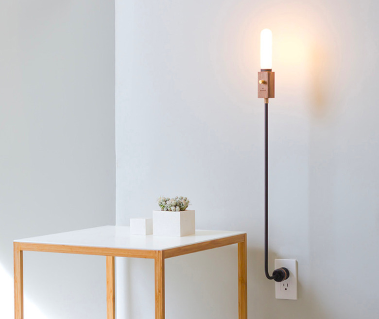
That's exactly the idea behind a split receptacle. The most common reason for installing one is to control a switched lamp on one of the outlet receptacles while leaving the other receptacle free for plugging in other appliances. One of the receptacles is fed by a wall switch while the other connects to a separate hot wire so it isn't controlled by the switch and is always on, or "hot." You can buy split receptacles at any hardware store, but it's easy to make your own by converting a conventional duplex outlet.
Why You Might Need a Split Receptacle
Why You Might Need a Split Receptacle
Every bedroom needs a light fixture that can be turned on and off by a switch located next to the door. This is a code requirement that guarantees safety for anyone entering the bedroom in the dark. In lieu of a hardwired room light fixture mounted on the ceiling or wall, the code allows you to provide an outlet controlled by a wall switch, into which you can plug a standing lamp or a table lamp. If your bedroom already has too few outlets, you may not want to sacrifice an entire receptacle just for the lights. Installing a split receptacle ensures that the electric clock or air purifier you plug into the free outlet stays on when you turn off the lights.
You can also use a split receptacle in any other room to get the same benefit, but some cautions apply. Any outlet served by a GFCI is not a good candidate for a split receptacle. If you break the bond between the two receptacles in a GFCI duplex, the outlet will not provide the required ground-fault protection.
Make Your Own Split Receptacle
Make Your Own Split Receptacle
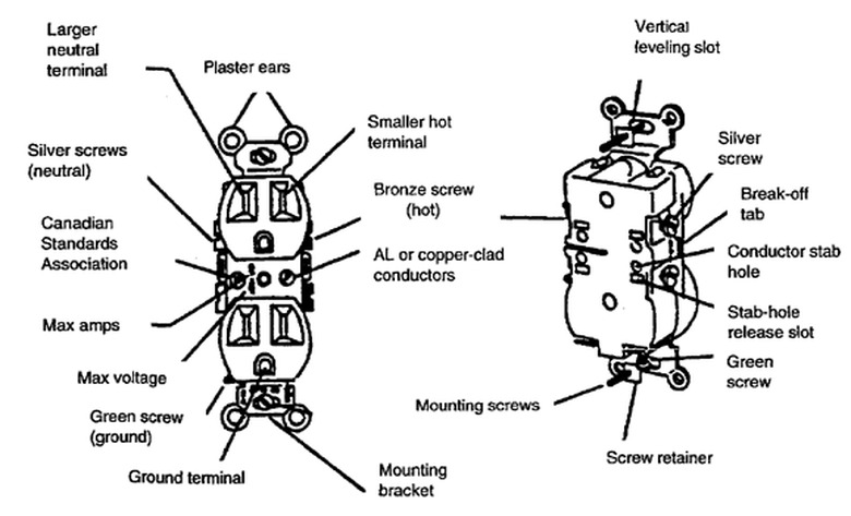
If you examine the sides of a conventional duplex receptacle, you'll find a pair of brass (hot) terminals on one side and pair of chrome (neutral) terminals on the other. You'll notice that the two brass terminals are connected to each other by a brass bonding plate. To turn this duplex receptacle into a split receptacle is to remove this plate to make the top and bottom halves independent.
The plate is designed to be breakable. You can usually snap it in two by forcing a flathead screwdriver underneath it and prying upward. However, you want to make sure the two halves of the plate remain far enough apart to prevent electrical arcing. It's better to remove the two brass terminal screws and their contact washers and either pull the bonding plate off or cut out a section of it with wire cutters.
Tip
When you install a split receptacle, you should mount it upside down—that is, with the ground pin facing up instead of down. This is a precaution that alerts anyone using the outlet to the fact that it's a split receptacle and not a conventional duplex receptacle
Wiring for a Split Receptacle Fed by a Single Circuit
Wiring for a Split Receptacle Fed by a Single Circuit
In most cases, the reason for installing a split receptacle is so you can control one of the outlets with a wall switch—which means you have to wire it to a switch. One strategy is to wire the switched outlet to one circuit and the always-on outlet to a different circuit altogether. It's possible, however—and probably more efficient—to wire both the switched and the unswitched outlet on the same circuit.
There are many ways the wiring can be configured, depending on where the switch is located along the pathway of the circuit, but to understand the wiring involved, it is easiest to consider a basic configuration in which a 2-wire feed cable enters the switch box from the power source, and a 3-wire cable continues onward to the outlet location.
Wiring a split receptacle is most often done by an electrician. If you do this work yourself, make sure you are confident of your wiring skills and always make sure that the power is off before you touch any circuit wires.
References
Wiring at the Switch Box
- In this sample configuration, the electrician cuts a 6-inch length of black wire and strips 1/2 inch of bare wire from each end to create a pigtail. Strip 1/2 inch of insulation from each end of the pigtail.
- Join one end of the pigtail to one of the screw terminals on the single-pole switch by looping the wire around the screw terminal and tightening it securely.
- Join the other end of the pigtail to both black circuit wires—the feed wire entering the switch box and the black wire from the three wire cable that extends onward to the outlet location. The feed wire an now supply both the switch and an "always-on" black wire running to the receptacle box.
- Connect the red wire from the three-wire cable to the other screw terminal on the switch. This secondary hot wire, controlled by the wall switch, can now control current to one half of the split receptacle located downstream.
- Join the white neutral circuit wires together in the switch box, using a wire connector.
- Finally, make the grounding connections at the switch box by cutting short bare copper pigtail wire and connecting one end to the green grounding screw on the switch. Join the other end of the grounding pigtail to both circuit grounding wires, using a wire connector. Note: if the switch box is metal, it will also need to be connected by a pigtail to the circuit grounding wires.
Wiring at the Receptacle Box
- Make sure the duplex receptacle has been "split" by breaking or removing the bonding strip on the hot side of the receptacle. This effectively severs the receptacle into two independent halves. Do not sever the bonding strip on the neutral side of the receptacle.
- Connect the bare copper grounding wire from the circuit cable to the green grounding screw on the receptacle. If the box is metal, it will also need to be connected to the circuit grounding wire with a pigtail.
- Connect the white neutral circuit wire to either of the neutral screw terminals on the duplex receptacle.
- Connect the black and red circuit wires from the three-wire cable to the two hot screw terminals on the duplex receptacle. The receptacle half that is connected to the red wire will be the one controlled by the wall switch; the other receptacle half will be "always on."
Finishing Up
Tuck the wires into the boxes at the switch and outlet locations, attach the devices to the wall boxes, and attach the cover plates. Turn on the power to the circuit at the main service panel, and check to make sure the outlet works correctly—one half controlled by the wall switch, the other half always hot.