How To Connect Single-Phase Electric Motors
Things Needed
-
Screwdriver
-
Dual-core AWG 14 wire (if connecting a DC motor), or
-
Tri-core AWG 12 wire (if connecting an AC motor)
-
Wire strippers
A single-phase electric motor is fairly simple in design, when compared to a three-phase motor. They are generally fitted in smaller electrical devices, such as power tools. A direct current (DC) single-phase motor starts turning automatically, once electricity is connected, but an alternating current (AC) single-phase motor needs a capacitor to initiate rotation. This is because AC current alternates about 60 times a second, so without a capacitor the motor would simple vibrate rather than rotate. A single-phase motor, whether DC or AC, is moderately simple to connect.
DC Electric Motor
Step 1
Remove the panel on the single-phase DC electric motor so you can access the terminal connectors. Use a screwdriver to remove the screws holding the panel in place, and then lift off using your fingers. There are two terminal connectors on a DC motor: live and neutral. Loosen the terminal connector screws using a screwdriver. Don't completely undo them.
Step 2
Strip 1 inch of outer plastic off the ends of a strip of dual-core AWG 14 wire using wire strippers so you get to the two internal wires colored red and black. Strip about ¼ inch of plastic off the ends of the two colored internal wires using wire strippers. This exposes the metal core.
Step 3
Slide the black wire under the terminal screw labeled "-," "N" or "Neu," and then tighten the screw. Slide the red wire under the terminal screw labeled "+," "Live" or "L," and then tighten the screw.
Step 4
Replace the terminal connector cover. Put the screws into the hole and tighten them. Use the same method to connect the opposite end of the wire to the power source, which for a DC motor is likely to be a transformer or battery pack, as they operate on low voltage.
AC Electric Motor
Step 1
Use a screwdriver to remove the screws holding the terminal connector panel on the AC single-phase motor. Remove the panel using your fingers. There are three connectors: live, neutral and ground. Loosen the three terminal screws using a screwdriver, but don't completely remove the screws.
Step 2
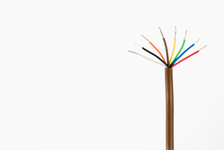
Strip 1 inch of outer plastic off the end of a tri-core strip of AWG 12-gauge wire to reveal three internal colored wires. The wires are green or green and yellow striped for ground, white or gray for neutral, and black, but sometimes orange or red, for live. Remove ¼ inch of colored plastic off the ends of the three wires.
Step 3
Slide the green wire under the terminal connector labeled "Gnd" or "T" and then tighten the screw. Slide the white wire under the terminal connector labeled "N," Neu" or "-," and then tighten the screw. Slide the black wire under the terminal connector labeled "L," "Live" or "+," and then tighten the screw.
Step 4
Replace the terminal connector panel. Insert the screws in the screw holes and tighten the screws.
Step 5
Put a plug on the opposite end of the wire, if one is not already attached. Strip the wire as previously described using wire strippers. Remove the plug cover using a screwdriver and then loosen the screws on the three terminal poles in the plug. Attach the green wire to the top terminal, attach the white wire to the lower left terminal and then attach the black wire to the lower right terminal. Tighten the terminal screws and replace the plug cover. Tighten the screw so the plug cover is held in place.